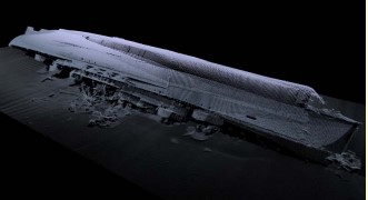
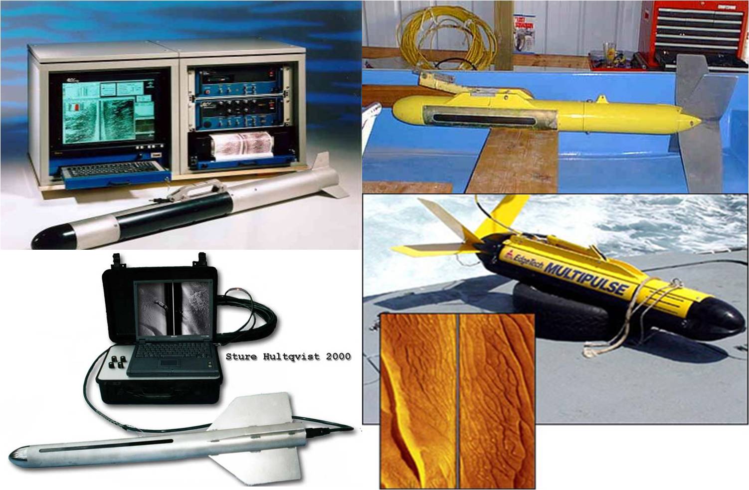
Active sonar systems for locating and capturing images of things on the bottom include Side-scan sonar (also sometimes called side scan sonar, sidescan sonar, side imaging sonar, side-imaging sonar and bottom classification sonar). The sonar’s various physical sensors, referred to as a transducer array, transmit and receive the sonic pulses that aid in charting the seafloor and object detection. This array may be fastened to the ship’s hull or mounted on various motor boats, such as a towfish.
- In the present, Hydrographic Survey of an area cannot be considered complete unless complete side scan sonar has not been carried out and all bottom contacts investigated.
- The side scan sonar gives the knowledge of all word obstructions on the seabed, and in many cases a full picture of the seabed type and texture.
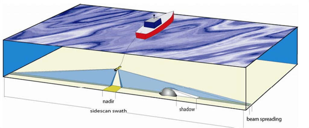
PURPOSE OF SIDE SCAN SONAR
In hydrographic surveying, side-scan sonar is used for four main purposes:
Wrecks and Obstructions Detection
- The detection of wrecks and obstructions between sounding lines. Although precise position and least depth cannot be determined by side-scan sonar, a properly tuned and operated sonar will detect nearly all significant wrecks and obstructions between lines.
Detection of Bottom Contacts
- Bottom connections are detected. When applied properly, side-scan sonar can detect extremely minute bottom contacts. While not dangerous to navigation, the placements of such objects, or groupings of objects, are critical in submarine and mine-warfare operations.
Identification of seabed mobile regions
- Identification of seabed mobile regions The existence of sandwaves and ripples indicates that the seabed in that location is mobile. On significant shipping routes, such places may need to be re-surveyed on a regular basis to guarantee navigational safety.
Gathering of bottom/ seabed texture information
- The collection of bottom texture data. The texture of the seabed, coupled with bottom samples, is essential during submarine bottoming and mine-warfare operations.

Side Scan Sonar Principle
- All sonar sets measure the time taken for the acoustic pulse to proceed to and return from a target.
- Most of them convert time intervals automatically into distance, assuming a fixed value for the speed of sound in water.
Basic Principle of Operation
Side scan sonars typically have narrow horizontal beamwidths (1 ° approx), with broader vertical beamwidths (40° approx) angled downward at 10°. Two frequencies of transmissions are often used, one for normal search operations and another, higher, frequency for very high resolution. The pulse repetition frequency is governed by the selected range. In a typical side scan sonar PRF varies with range as:
0-75m scale 10 pulses per second (pps)
0-150m scale 5 pps
0-300m scale 2.5 pps

The fish is about 1m long containing two sets of transducers that can scan the seabed on either side and horizontal width of the beam is narrowed down to 1,2˚. Moreover, transducer of side scan sonar can be fixed to the hull of the vessel
Theoretical Considerations
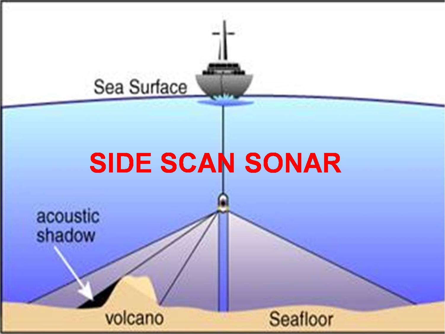
All side scan sonars transmit and receive acoustic pulses of energy. Most of the energy arriving onto the seabed is scattered forward in the specular (reflected) direction, with some energy absorbed by the seabed itself. However, a small portion of energy is scattered back to the sonar, amplified and recorded. The time shift between the transmission and reception is directly proportional to the distance between the sensor and its target (the slant range). Signal amplitude is related to the amount of backscattering from the seabed.
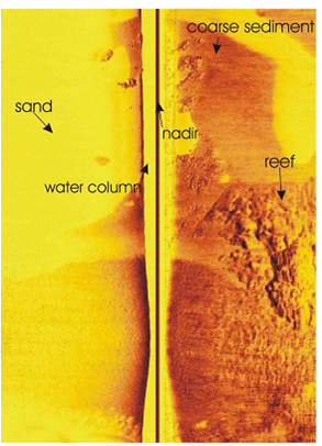
Material properties of the area being scanned determine the acoustic reflectivity of that section of seabed. Rock and gravel are better reflectors than sand or mud and will therefore show up darker on the final sonar record (sonograph). Seabed topography also determines the reflected energy strength from the sonar beam. Up slopes facing the towfish are far better reflectors than down slopes because of the lower angle of incidence of the sonar pulse as it encounters the seafloor. Topography with a lower angle of incidence appears dark on the record.

Systems of Side Scan Sonar
- A transducer which is known as the “fish”.
- A steel wire reinforced care line acting as transmission and tow cable.
- A dual channel recorder.

- A dual channel recorder.
Survey Technique
Side scan sonars are normally towed some distance astern of the vessel on an armored cable. This has the advantage that the transducer (towfish) is mechanically and to a certain extent, acoustically decoupled from the ship and is therefore not subject to the same movements as a hull mounted sonar. The assumption is usually made that the fish is completely stable in roll, pitch and yaw, although some motion in all these planes undoubtedly occurs. Roll probably has relatively little effect on the sonar picture, being compensated for by the wide beam angle in the vertical plane. A permanent list in one direction, which may be caused by a distorted fin or a twist in the cable, can however markedly decrease performance. Pitch and yaw are more significant; with such a narrow beam-width in the horizontal plane, these motions could decrease detection probabilities of small targets. A target that would receive at least 5 pulses with a stable fish may only receive 3 or 4 if the fish is oscillating in either of these directions.
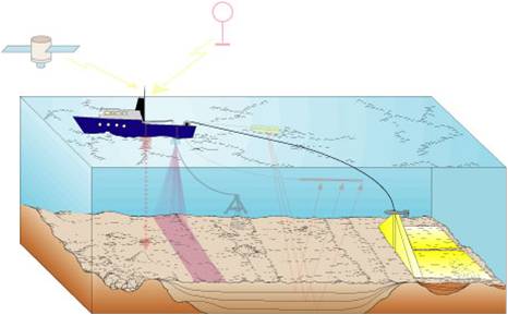
Procedure to Operate Side Scan Sonar
To prepare for SSS operation, put all equipment to the weather deck or outer deck so that Fish may be readily lowered. Following that, extra cable must be laid out on deck prior to lowering equipment. Furthermore, restrict ship/boat speed to 5 knots to avoid any mishaps when reducing SSS. Remember to attach the fish to the recorder and turn it on before surveying.
- TOW-FISH Launching Procedure Examine the water depth in the survey region using a chart or an echo sounder. Set the ship on a straight course at a speed of 4 to 5 knots. Place two fish in water and pay out a length of cable equal to the depth of the water. On the reorder, a sea bed echo should occur.Pay out additional cable till you reach the desired towing height.
- Considerations in Sidescan Sonar Operation
- Frequency, range and resolution
- –Low Frequency
- –High frequency
- Range of geometric considerations
- Full coverage of the seabed
- –100% overlap
- Suitable height above the seabed
- Frequency, range and resolution
- Survey Speed and Ping Rates
- The ping rates of equipment are selected by the operator and are generally limited by the range in use
- For longer ranges, the backscatter signals will take longer to be received and the delays between pings will be greater
- Side scan sonars are normally towed at 4 to 6 knots

- Positioning, Sidescan Deployment and Sea Conditions
- Although sidescan sonar is normally thought of as being deployed as a towed body, it can also be mounted on the hull of a vessel
- Towing has a further disadvantage that it is difficult to predict the horizontal position of the fish with reference to the GPS antenna on the surface
- This really relates to attempts to predict the horizontal distance the fish is behind the vessel known as the ‘layback’.
- Sea condition also affects the operation of sidescan sonar

- Even vessel mounted systems with sophisticated positioning have a limit of conditions
- SONAR LINES -SPACING DIRECTION AND SPEED
- Standard sonar line spacing will be ordered in the HI by the sonar category. The vast majority of continental shelf surveys will be on a scale of 1: 25 000, which is chosen to match an effective sonar range of 150 meters. Line spacing will therefore be 125 meters, which gives a theoretical overlap of 25 meters under adjacent lines.

- The aim must be to fly the towfish above the seabed at a height of 10% of the range scale in use.
- Before surveying commences in an area, the surveyor must be satisfied that the effective sonar range is being achieved. A sonar confidence check must therefore be conducted using a suitable bottom contact at various ranges.
- Sonar line direction should be planned to be coincident with the predominant tidal stream in all cases. Sidescan sonar should also be streamed during the running of crosslines, ideally when the tidal stream is at its weakest.
- Sandwaves tend to lie at right angles to the direction of the tidal stream. This will provide good bathymetric profiles, but inadequate sidescan sonar imagery. Consideration should be given to running some sonar lines along the sandwave crests to detect the pattern of the field. These lines should of course be run when the tidal stream is at its weakest.
- Sonar interlines should be run whenever poor track-keeping causes the vessel to deviate from the survey line such that a gap of more than 140 meters exists between two adjacent lines, when 125 meters line spacing is planned.
- Sonar investigation lines will be required at a shorter range scale for all significant sonar contacts or shoals where the highest point (shoalest depth) does not lie on standard spaced lines.
- Sonar cover must extend so that the whole of the surveyed area receives two full sonar sweeps. This means that sonar lines must be extended to ensure that the towfish and its beam crosses the limit of the area.
TOW-FISH Positional Errors
If there is no tidal stream, but a wind is blowing sufficiently strongly to cause the vessel to have a significant difference between course steered (CS) and course made good (CMG), the tow point of the vessel will be displaced from the track by the sine of the angle between CS and CMG multiplied by the distance between pivot point to tow point. Because the tow point will follow the CMG, the tow cable will lie parallel to the CMG, and the towfish will be displaced by an equal amount. So long as the wind direction remains reasonably constant, this displacement will always be on the side away from the wind, and the overlap between adjacent lines should normally permit standard line spacing to be maintained.
Example
Course 352
Wind 300 @ 20 knots
SMG 6.5 knots
CMG 000
Pivot to Tow point = 40m
Offset = sin8° x 40m = 5.5 meters.
Return line
CMG 000
SMG 6.5
Course 190
Offset = sin 100 x 4Om = 6.9 metres. (6)
Very strong beam winds may cause the sonar line spacing to be reduced.

